Autocalibration Procedure is Implemented
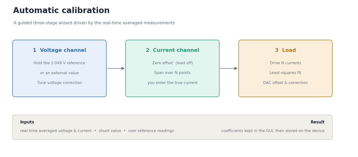
Every OpenEPT board leaves the bench slightly different: the ADC reference, the divider tolerances, the shunt and the current-sink offset all shift the numbers a little. Until now these differences were corrected by typing calibration coefficients into the Calibration window by hand, accurate only if you knew what each coefficient meant and had a reference instrument next to you. This milestone replaces that with a guided autocalibration wizard that walks the user through the voltage channel, the current channel and the programmable load, computes every coefficient from the live measurements and the user's reference readings, and writes a short report of what it changed. This post is the implementation report: how the calibration data is shared, how the wizard state machine is organised, the maths behind each coefficient, and the firmware parameters that make the result persistent.
In This Update
- What the Calibration Corrects: the measurement and load models, and which coefficient each stage tunes.
- Voltage Reference: the on-board 2.048 V reference and the J12 input selection.
- Shared Calibration Data: one object behind the window, the wizard and the processing path.
- The Wizard State Machine: stages, steps, detection, and per-channel restart.
- The Maths of Each Stage: voltage correction, current offset and span, load fit.
- Driving the Load Safely: protections, the load path, and why it bypasses the energy control window.
- Firmware: Making it Persistent: the calibration parameters and the control protocol.
What the Calibration Corrects
Before describing the procedure it helps to see exactly which number each stage moves. The GUI reconstructs voltage and current from the raw ADC codes with a small set of calibration coefficients:
voltage [V]  = voltageOffset + raw_v * (Vref / 2^res) * voltageCorrection
current [mA] = (raw_c * (Vref / 2^res) - voltageCurrentOffset) / (shunt * gain)
               * 1000 * currentCorrection
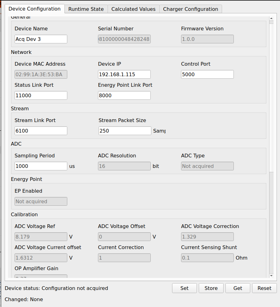
So the voltage channel is a gain term (voltageCorrection) and an offset (voltageOffset); the current channel is an offset that zeroes the reading (voltageCurrentOffset) and a gain that scales it (currentCorrection). The programmable load is the inverse path, where a requested current is turned into a DAC code, and the firmware shifts it with its own pair before the conversion:
DAC current [mA] = requested * loadDacCorrection + loadDacOffsetThe autocalibration tunes exactly these: voltageCorrection in the voltage stage, voltageCurrentOffset and currentCorrection in the current stage, and loadDacCorrection / loadDacOffset in the load stage. Everything else (the reference, the shunt, the amplifier gain) is a measured property of the board and is left untouched.
Voltage Reference
Both the voltage and the current channels are calibrated against a known voltage, and the board can obtain that voltage in two ways. On-board there is a 2.048 V precision reference (a MAX6126) that derives the VOLTAGE_REFERENCE line from the 3V3 supply:
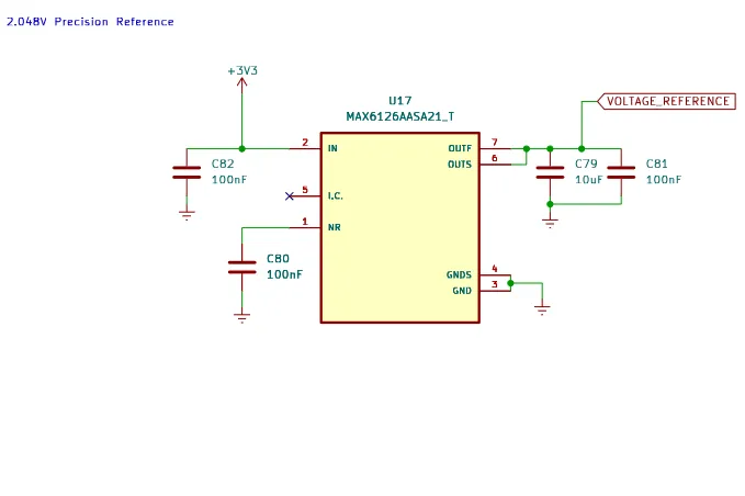
Which voltage the ADC actually measures is chosen by the ADC IN Selection jumper J12, which routes the ADC voltage input either from the battery divider (VBAT_ADC) or from the reference line (VOLTAGE_REFERENCE):
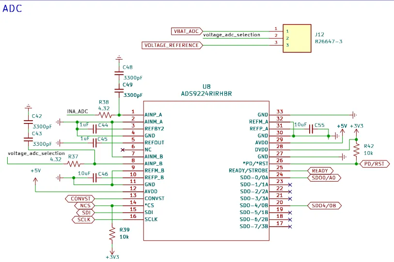
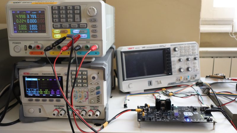
This is what makes the two reference options possible. For a voltage-only calibration, point J12 at the internal 2.048 V reference, which needs no external equipment. For a full voltage, current and load calibration, an external generator supplies a known voltage on the input and keeps the board energized while the load sinks current; the wizard's external value option is used then. The step-by-step for the external case is covered in the companion guide, How to Perform the Calibration Procedure.
Shared Calibration Data
The whole procedure rests on one design decision: the Calibration window, the autocalibration wizard and the live acquisition path all point at the same CalibrationData object. Device::getCalibrationData() returns the instance owned by the processing stage, and both windows are handed that pointer:
void DeviceWnd::setCalibrationData(CalibrationData *data)
{
    calibrationWnd->setCalibrationData(data);
    autoCalibrationWnd->setCalibrationData(data);
}
Because the acquisition path reads its coefficients from the same object, the instant the wizard changes voltageCorrection and asks the device layer to recompute its increments, the next averaged measurement already reflects the new value. This is what makes the voltage and current stages verifiable in real time: the wizard changes a coefficient, then simply watches the same averaged number it is calibrating converge to the target. The coefficients live only in the application until the user presses Store in the Calibration window; autocalibration never writes to the device by itself.
The Calibration window itself was rebuilt for the occasion. It is no longer modal, so the main Device view stays reachable while it is open, and the fields are grouped into General ADC configuration, Voltage channel calibration, Current channel calibration and Load calibration, with a single Start auto calibration button that launches the wizard.
The calibration GUI lives in the OpenEPT GUI repository:
- Calibration window:
Windows/Device/calibrationwnd.cpp - Autocalibration wizard:
Windows/Device/autocalibrationwnd.cpp - Calibration data:
Processing/calibrationdata.h
The Wizard State Machine
The wizard is a small state machine fed by one signal: the real-time averaged voltage and current that the processing stage already emits for the statistics panel. Every averaged sample is pushed into a short history; a step advances only when that history is stable (its spread stays inside a limit) and inside the band the step expects. There is no busy-waiting and no separate measurement path.
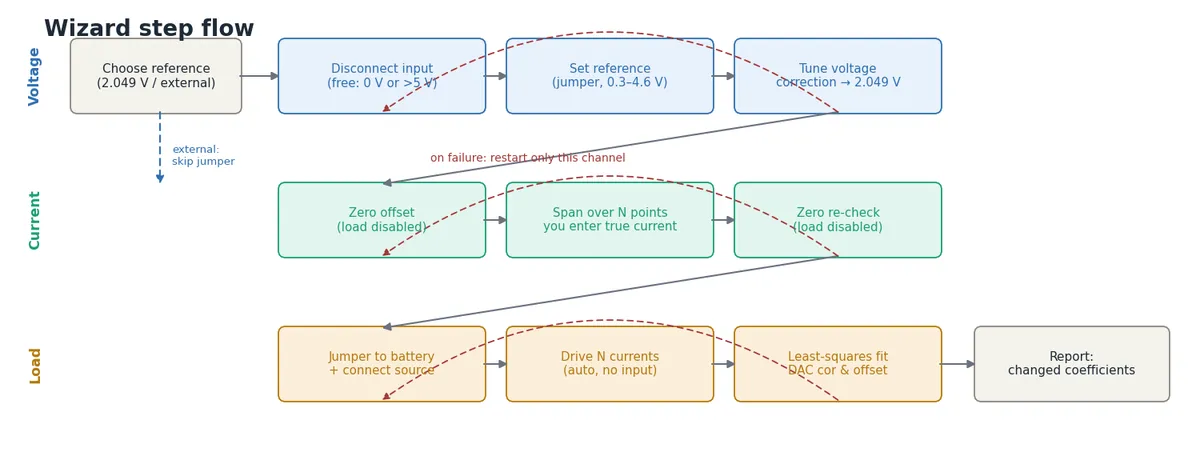
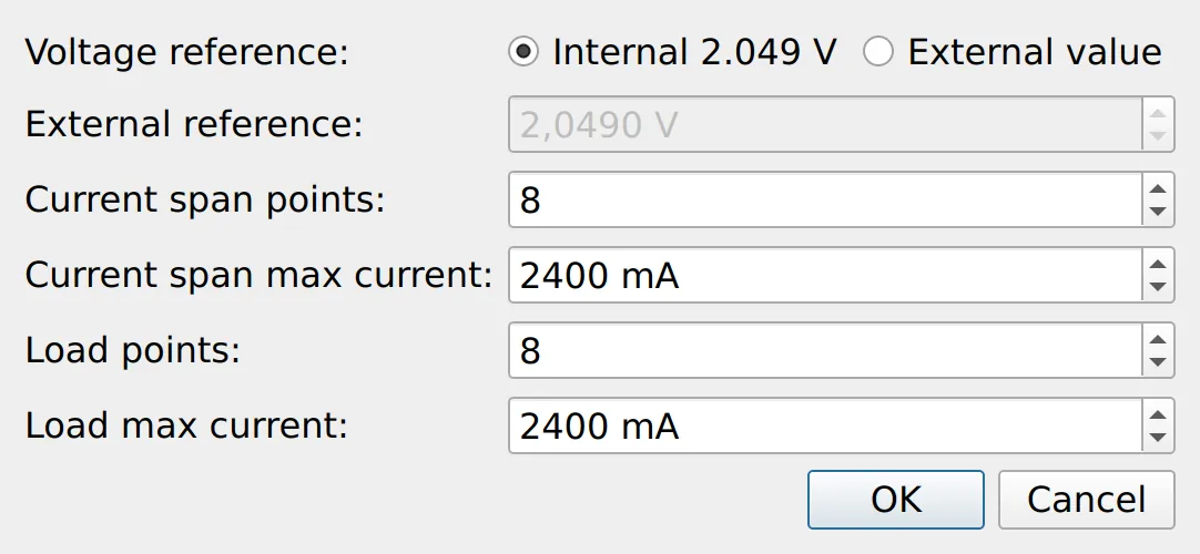
At start the wizard opens a single setup window that collects everything it needs in one place: which reference is used (the internal 2.049 V or an external value held on the input), and, for both the current span and the load, how many points to drive and the maximum current to reach. The reference choice reshapes the flow: with an external reference the input already carries the known value, so the disconnect-and-switch-jumper steps are skipped and the voltage stage begins tuning immediately. The two maximum currents default to 80 % of the board's shunt-derived limit and are capped at that limit, so a sweep can never ask for more than the hardware can sink.
Detection uses two bands. A free input reads either near zero or above the measurement range, so both < 0.1 V and > 5 V count as disconnected, which turned out to matter because on this hardware an open input floats high rather than falling to zero. A connected reference or source has to sit in a sensible band (0.3 V to 4.6 V, widened to 1.5× the reference for high external values). The steps that wait for the user also carry an "I am ready, continue" button, so the operator can confirm a step manually instead of waiting for the automatic detection.
When something goes wrong (the reference drifts out of band during tuning, the load will not draw current, the user cancels a span reading), the wizard does not start over from scratch. modeStartStep() maps the current step back to the beginning of its own channel, so a load problem re-runs only the load stage and the voltage and current coefficients already found are preserved.
The Maths of Each Stage
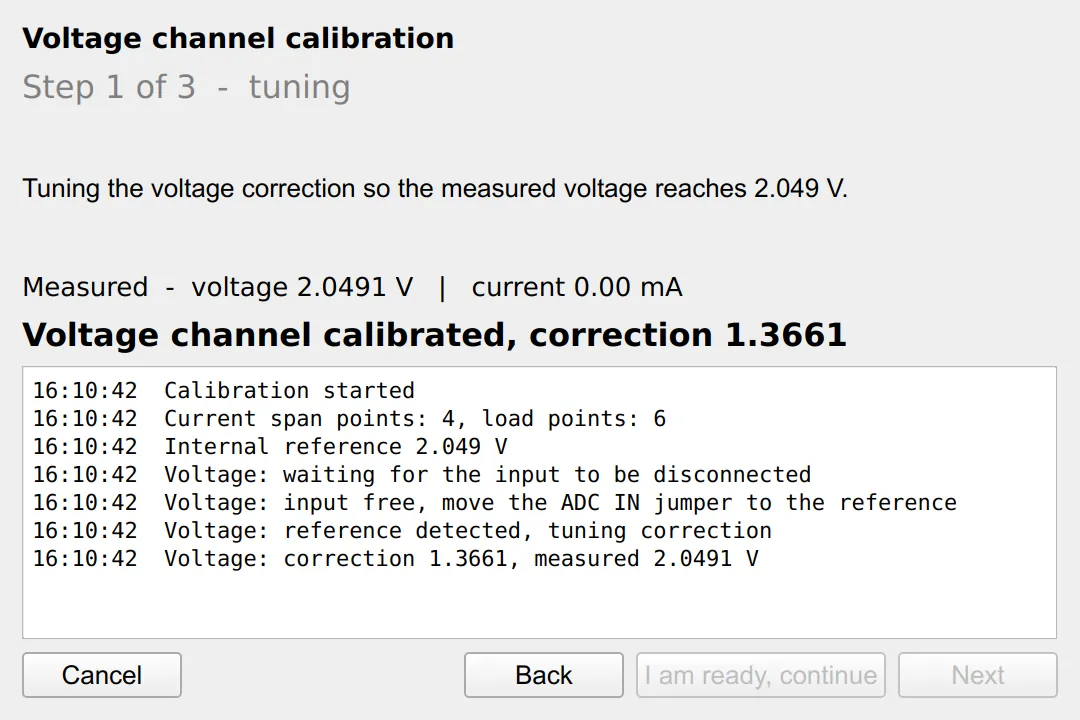
Voltage channel. The measured voltage scales linearly with voltageCorrection, so the correction that lands on the reference is a single ratio, with no iterative search:
calData->voltageCorr = calData->voltageCorr * referenceVoltage / mean;
emit sigApplyCalibration();
After applying it the wizard waits for the averaged reading to settle and accepts the channel when it is within a few millivolts of the reference. The disconnect and jumper steps that precede it detect the board state on their own, and the live line and log make every reading visible as the channel converges.
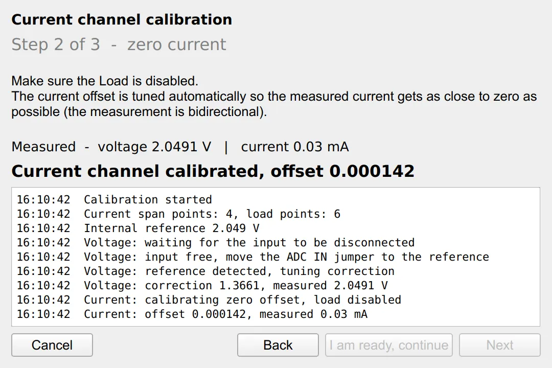
Current channel, zero. With the load disabled the current should read zero. The offset is in volts, so the measured current is converted back and used to shift voltageCurrentOffset. The acceptance test is symmetric around zero, since the measurement is bidirectional, so the goal is the closest reading to zero, not the first one that crosses it:
calData->voltageCurrOffset += mean * (calData->currentShunt * calData->currentGain)
                              / (1000.0 * calData->currentCorrection);
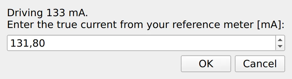
Current channel, span. This is the part that needs a reference instrument. The wizard drives the load across several currents and, at each point, asks the user for the true current read on their meter. It never assumes the requested current is correct; only the user's reading is trusted. Because the offset is already zeroed, the current measurement is a pure scale, and the best scale over all points is the least-squares slope through the origin:
spanSumMT += measured * trueCurrent;
spanSumMM += measured * measured;
...
double scale = spanSumMT / spanSumMM;
calData->currentCorrection = calData->currentCorrection * scale;
A final zero re-check, again with the load disabled, confirms the offset after the span has moved the scale, and only then does the current channel hand over to the load stage.
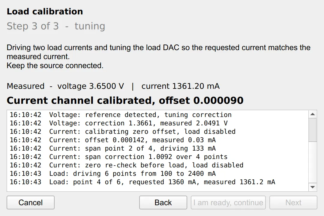
Load. With the current channel now trusted, the load calibration needs no per-point input. The wizard drives a set of requested currents from 100 mA up to the maximum chosen in the setup window and records what the (now calibrated) current channel measures. That maximum defaults to 80 % of the board's limit, which comes from the shunt: a 0.045 Ω shunt corresponds to 3 A, so the full scale scales inversely, and this value is the hard cap the setup window clamps to:
double maxCurrent = 135.0 / shunt; // 0.045 -> 3000 mA, 0.5 -> 270 mA
With the configured point count spread across that range, a least-squares line through all of them gives the slope and intercept of measured-vs-requested. Inverting the firmware's requested * cor + off relation yields the new pair:
calData->dacCorrection = oldCor / slope;
calData->dacOffset     = oldOff - intercept * oldCor / slope;
When every channel is done the wizard prints a report that lists only the coefficients that actually changed, old value next to new, and reminds the user to press Store to keep them on the device.
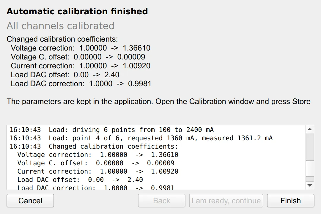
Driving the Load Safely
Enabling the load from a calibration wizard is the one place where things can go wrong on real hardware, so the load path was built to be robust rather than convenient.
First, it does not go through the Energy Control window. That window refuses load commands unless its working mode is set, which has nothing to do with calibration; the wizard drives the output directly through the device layer (device load enable together with device dac enable set), so the calibration never depends on an unrelated UI state. The load stage is off by default, so both the load stage and the DAC are enabled together before any current is expected.
Second, protections are expected to trip while a source is being connected, so instead of refusing, the wizard resets the latch before enabling the load and logs it; any protection that fires during the procedure is reset automatically. If the load still cannot draw current, the fit sees a flat response and the load stage restarts with a clear message.
Throughout, a log panel inside the wizard records every transition and every detection with its measured value, so the whole run (what was detected, which coefficient moved and to what, where a protection tripped) stays visible as a history.
Firmware: Making it Persistent
The coefficients the wizard produces are the same ones the firmware already stored for the voltage and current channels; the load pair is new. On the firmware side the load DAC offset and correction are two calibration parameters, read once when the Load service starts and applied in the current-to-voltage conversion:
static float prvLOAD_CurrentToVoltage(uint32_t current)
{
    float compensated = (float)current * prvLOAD_DATA.dacCorrection + prvLOAD_DATA.dacOffset;
    if(compensated < 0.0f) compensated = 0.0f;
    return (compensated / 1000.0f) * 8.8f * 0.075f;
}
The control protocol carries them alongside the existing calibration values: device param cal get now reports DACOFF and DACCOR, and device param cal set accepts -dacoff and -daccor. Both are optional, so an older application still interoperates, and both are stored to the file system with the rest of the calibration when the configuration is saved. That is exactly what Store triggers after an autocalibration run: the coefficients kept in the GUI are sent down and persisted, so the board keeps its calibration across power cycles.
The firmware side of the load calibration is in the OpenEPT Firmware repository:
- Load current conversion and DAC parameters:
Middlewares/Services/Load/load.c - Calibration parameter protocol:
Middlewares/Services/Control/control.c - Calibration parameter definitions:
Middlewares/Services/Configuration/configurationDef.c
What Comes Next
The procedure currently tunes the gain of each channel and the two offsets; the voltage offset is left at its measured default. A natural next step is a zero-voltage point in the voltage stage to tune voltageOffset the same way the current offset is handled. The wizard is also a good place to store a short calibration history (date, board, and the before/after coefficients it already reports), so a board's calibration can be traced over time rather than only applied.