How to Perform the Calibration Procedure
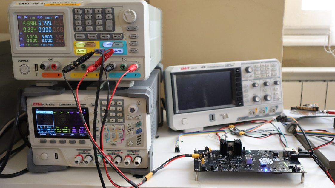
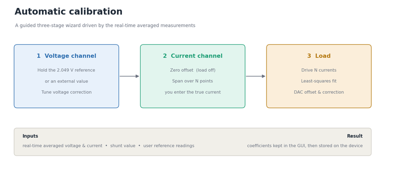
This guide walks through calibrating an OpenEPT Energy Profiler Probe (EPP) end to end, on a real board, using the automatic calibration wizard. It is a practical companion to the implementation write-up, Autocalibration Procedure is Implemented, which explains what happens inside the wizard; here we simply do it.
What you need depends on what you want to calibrate:
- Voltage, current and load (the full procedure shown here): an external voltage generator is required. It supplies the known voltage the voltage channel is tuned against, and it keeps the input energized so the load can sink current while the current and load channels are calibrated.
- Voltage only: the board's internal 2.049 V precision reference is enough; no external equipment is needed. See the voltage-reference section of the implementation post for how that reference is wired.
In this example we calibrate all three channels, so we use an external generator set to 3.799 V.
How the wizard works internally: Autocalibration Procedure is Implemented
1. Bench setup
Connect the board and the external voltage generator, and start the acquisition in the GUI. The automatic calibration uses the real-time averaged voltage and current, so acquisition must be running before you start.
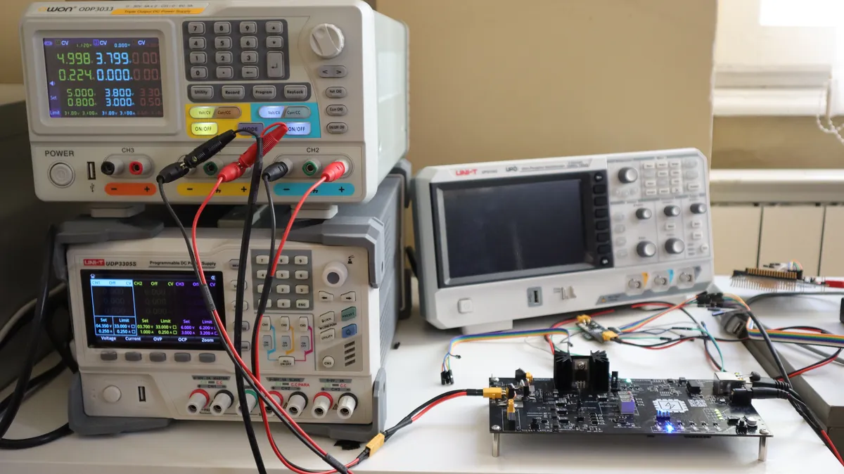
2. Select the reference input with jumper J12
The ADC voltage input is routed either from the battery divider or from the reference line, and that choice is made with the ADC IN Selection jumper J12. For calibration with an external generator, set J12 so the ADC reads the voltage reference input.
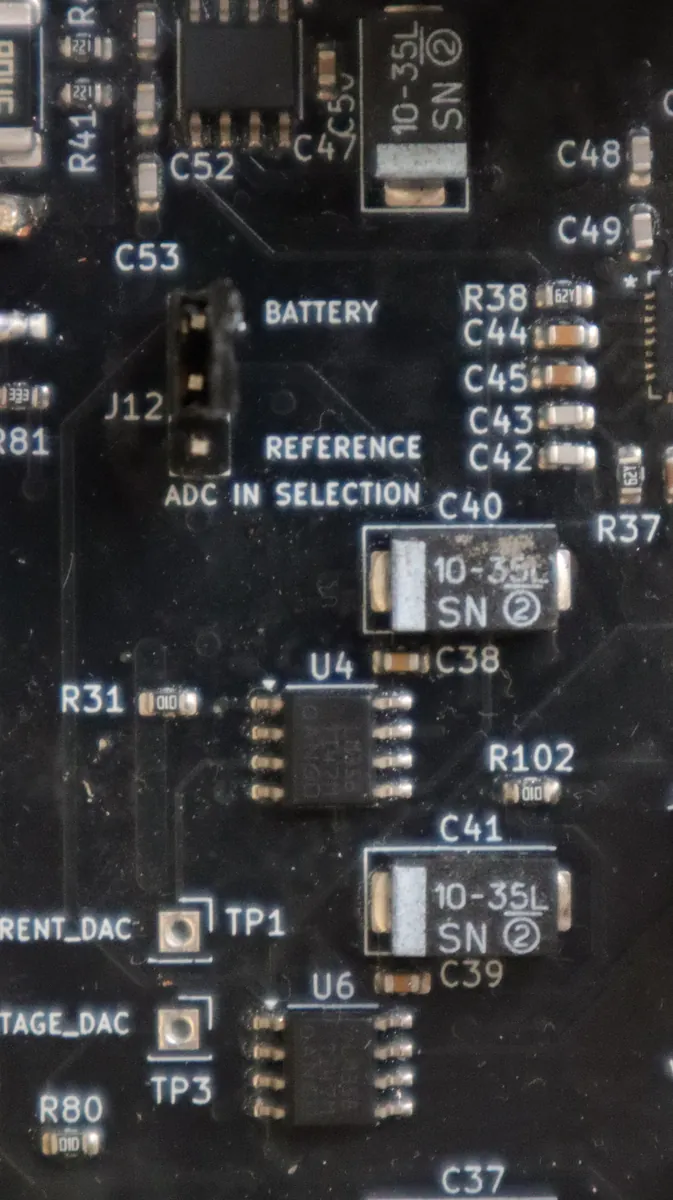
3. Set the generator voltage
Set the external generator to the voltage you will calibrate against. Here it is set to 3.799 V with no load current drawn yet.
4. Start the wizard and configure the run
Open the Calibration window and press Start auto calibration. A single setup window opens; fill it in as follows:
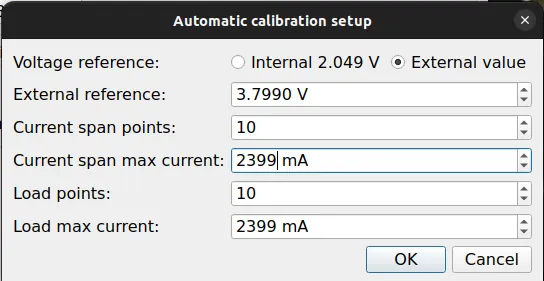
- Voltage reference: External value, set to 3.799 V. This is the voltage held on the input by the generator. Choosing an external value skips the disconnect and jumper prompts, so the procedure runs straight through.
- Current span points: 10 and Load points: 10 set how many currents are driven in each stage.
- Maximum current: 2399 mA for both the span and the load, the upper current the sweeps reach (capped at the board's maximum).
Press OK to begin.
5. Voltage channel
The wizard first tunes the voltage correction so the measured voltage matches the reference. There is nothing to do here; it adjusts the coefficient and waits for the reading to settle. In this run the correction moved to 1.33072 and the channel was accepted at a measured 3.799 V, matching the generator exactly.
6. Current channel: zero
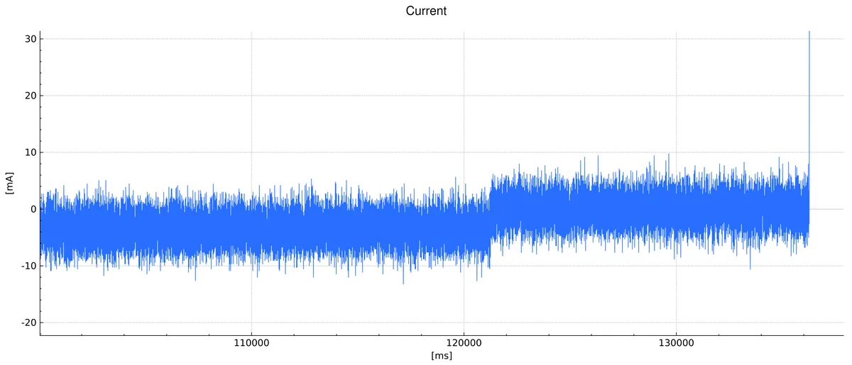
With the load disabled, the current should read zero. The wizard tunes the current offset until the measurement sits on zero. The graph below shows the effect: the current trace starts biased low (around −3.5 mA) and, once the offset is applied, recenters on 0 mA.
7. Current channel: span
Now the wizard drives a series of known currents through the load and, at each point, asks you to type the true current you read on the generator. This is what calibrates the current measurement: the wizard compares what it measures against your reference reading, not against what it requested.
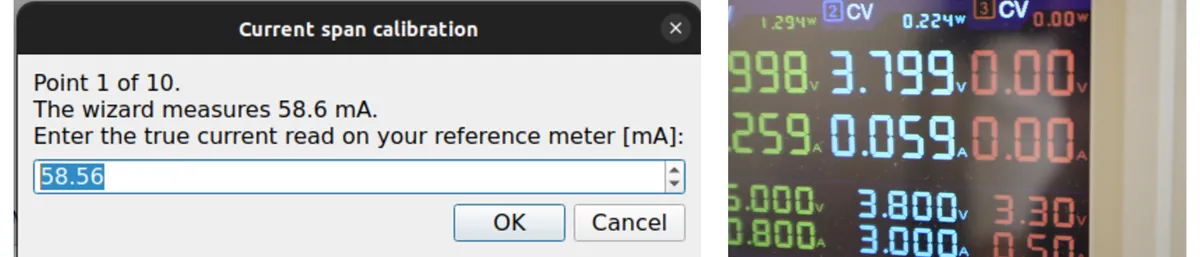
Enter the generator reading at each of the ten points. After the last point the wizard computes the current correction (here 0.99865) and does a final zero re-check before moving to the load.
8. Load channel
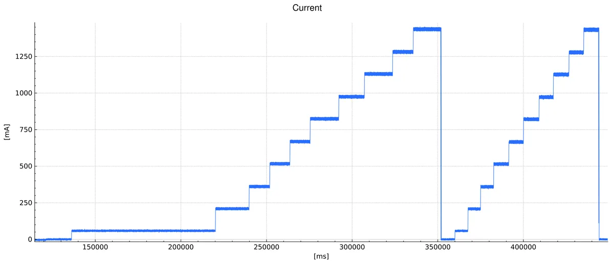
With the current channel now trusted, the load calibration runs on its own, with no input needed. The wizard drives the ten load currents and records what the calibrated current channel measures, then fits the load DAC. The capture below shows both staircases: the current span sweep first, then the load tuning sweep.
9. Results
When all three channels are done, the wizard reports the coefficients it changed, old value next to new.
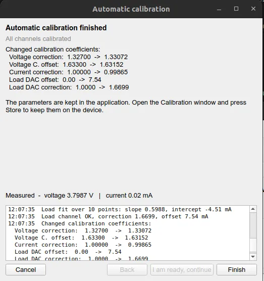
For reference, the complete log of this run:
Calibration started
Current span: 10 points, max 2399 mA
Load: 10 points, max 2399 mA
External reference 3.7990 V, jumper steps skipped
Voltage 3.7884 V, correction -> 1.33072
Voltage channel OK, measured 3.7990 V
Current -3.50 mA, offset -> adjusting
Current zero OK, measured -0.03 mA
Source detected at 3.799 V
Current span: 10 points from 100 mA to 2399 mA, you enter the reference at each
Span point 1: measured 58.56 mA, reference 59.00 mA
Span point 2: measured 210.09 mA, reference 210.00 mA
...
Span point 10: measured 1436.77 mA, reference 1434.00 mA
Current correction -> 0.99865
Current zero re-check OK, measured -0.09 mA
Load tuning: 10 points from 100 mA to 2399 mA (max 2999 mA)
Load fit over 10 points: slope 0.5988, intercept -4.51 mA
Load channel OK, correction 1.6699, offset 7.54 mA
Changed calibration coefficients:
  Voltage correction:  1.32700  ->  1.33072
  Voltage C. offset:   1.63300  ->  1.63152
  Current correction:  1.00000  ->  0.99865
  Load DAC offset:     0.00     ->  7.54
  Load DAC correction: 1.0000   ->  1.6699
All channels calibrated
10. Finish and save
Press Finish. The new coefficients are written into the Calibration window, where you can review them.
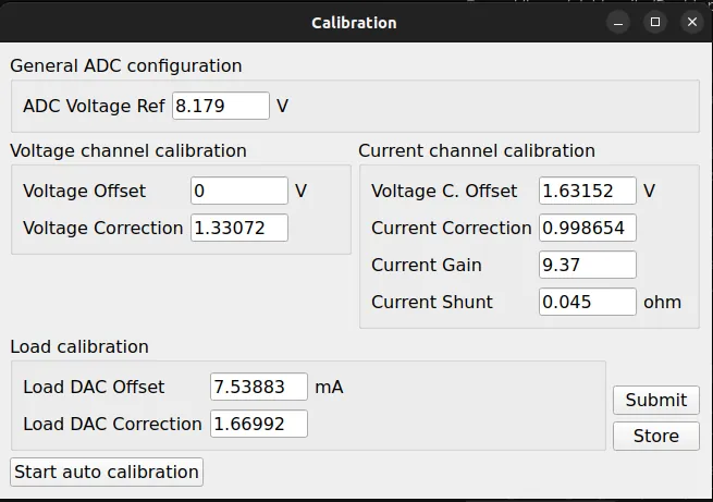
Two buttons decide what happens next:
- Submit: apply the coefficients to the running device now. They take effect immediately but are not persisted; a power cycle loses them.
- Store: write the coefficients to the device's file system permanently, so the board keeps its calibration across power cycles.
For a one-off check, Submit is enough; to finish the calibration for good, press Store.