Introducing the Next Generation of the OpenEPT Energy Profiler
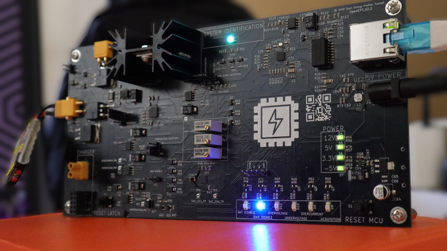
After several hardware and firmware revisions, we have completed a new version of the OpenEPT Energy Profiler. The new board keeps the measurement architecture of the previous prototype, but adds features that we found were needed during development and testing: programmable protection thresholds, persistent configuration storage, a cleaner configuration workflow in the GUI, and an interface for an external battery charger board.
What's New?
The new Energy Profiler introduces several important features compared with the previous hardware and firmware generation:
- Programmable protection configuration, allowing protection parameters to be adjusted according to the connected device, battery, and measurement scenario.
- On-board EEPROM storage for persistent storage of configuration parameters.
- Improved configuration management, allowing parameters to be read from, written to, cleared from, and exported from the device.
- Enhanced GUI support for configuring the Energy Profiler and managing stored configuration parameters.
- Dedicated charger board connection, extending the platform with battery charging capabilities.
- Improved hardware and firmware integration, providing a more complete foundation for energy profiling and battery-powered embedded-system experiments.
The main goal of these changes was to make the profiler easier to configure for different devices, batteries, and measurement setups without requiring hardware modifications for every change.
The redesigned OpenEPT Energy Profiler is not only available as an open-source hardware platform, the current EPP board can also be obtained as a ready-to-use device for development, research, testing, and energy-profiling applications.
If the standard board does not fully match your requirements, the Energy Profiler can also be customized for a specific application. This may include adaptations of the measurement range, connectors and interfaces, protection limits, battery-related functionality, or other hardware and firmware features required by a particular setup.
Whether you need the current EPP version or a customized Energy Profiler for your application, feel free to contact us to discuss the requirements.
In This Update
This development update covers three major areas of the new OpenEPT Energy Profiler:
- Hardware Bring-Up Firmware – dedicated firmware for systematic validation and testing of the newly manufactured Energy Profiler hardware.
- Firmware and GUI Upgrade – firmware and graphical interface improvements supporting programmable range control, configuration management, and persistent parameter storage.
- Hardware Redesign – redesigned Energy Profiler hardware incorporating programmable protection, EEPROM storage, charger-board connectivity, and other hardware improvements.
Hardware Bring-Up Firmware
As part of the development of the new OpenEPT Energy Profiler hardware, a dedicated hardware bring-up firmware mode was introduced to provide a systematic and reproducible procedure for testing newly assembled PCBs and validating communication with the main on-board components.
During the bring-up procedure, the Energy Profiler Probe is powered and connected to a host computer through a USB-to-UART adapter. The UART connection is used to monitor the bring-up log in real time, while the on-board LEDs provide additional visual feedback about the board status and individual protection signals. This setup allows each stage of the bring-up sequence to be followed directly while the newly assembled board is being tested.
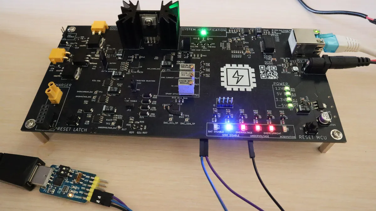
Instead of maintaining a separate firmware project exclusively for PCB testing, the bring-up functionality is integrated directly into the main OpenEPT firmware codebase. A single global compile-time configuration flag, CONF_BRINGUP_ENABLE, determines whether the project is built as the standard OpenEPT application or as a dedicated hardware bring-up firmware image.
#define CONF_BRINGUP_ENABLE 1
When CONF_BRINGUP_ENABLE is set to 0, the firmware follows the standard OpenEPT initialization procedure and starts the complete application stack. When it is set to 1, the normal system initialization is bypassed and the dedicated bring-up service is started instead:
system_status_t SYSTEM_Init()
{
#if(CONF_BRINGUP_ENABLE == 0)

    prvSYSTEM_DATA.state = SYSTEM_STATE_INIT;

    if(xTaskCreate(prvSYSTEM_Task,
                   SYSTEM_TASK_NAME,
                   SYSTEM_TASK_STACK_SIZE,
                   NULL,
                   SYSTEM_TASK_PRIO,
                   &prvSYSTEM_TASK_HANDLE) != pdTRUE)
    {
        return SYSTEM_STATUS_ERROR;
    }

    ...

#else

    BRINGUP_Init();

#endif

    return SYSTEM_STATUS_OK;
}
With this flag enabled, the same firmware project is used for PCB bring-up instead of maintaining a second test project. This also means that bring-up runs the same low-level drivers that are later used by the normal application.
The complete source code required for the hardware bring-up procedure is available in the OpenEPT Git repository. The main implementation is located in Source/ADFirmware/CM7/Core/Middlewares/Services/System/Bringup and consists of the following files:
bringup.c– implementation of the bring-up task and individual hardware validation routines.bringup.h– public interface and definitions of the bring-up service.
The global compile-time configuration used to enable the bring-up firmware is defined in the project configuration file:
globalConfig.h– contains theCONF_BRINGUP_ENABLEconfiguration flag used to switch between the standard OpenEPT firmware and the dedicated hardware bring-up mode.
For convenience, a prebuilt bring-up firmware binary is also provided. This allows a newly assembled Energy Profiler board to be tested without rebuilding the complete firmware project. The binary can be downloaded from:
Download the OpenEPT Energy Profiler latest bring-up firmware
After programming this image to the Energy Profiler, the board starts directly in bring-up mode and executes the hardware validation sequence described above.
Automated Hardware Validation
When bring-up mode is enabled, BRINGUP_Init() creates a dedicated FreeRTOS task responsible for executing the hardware validation sequence.
bringup_status_t BRINGUP_Init(void)
{
    if(xTaskCreate(prvBRINGUP_Task,
                   BRINGUP_TASK_NAME,
                   BRINGUP_TASK_STACK_SIZE,
                   NULL,
                   BRINGUP_TASK_PRIO,
                   &prvBRINGUP_TASK_HANDLE) != pdTRUE)
    {
        return BRINGUP_STATUS_ERROR;
    }

    return BRINGUP_STATUS_OK;
}
The bring-up sequence validates the essential hardware blocks of the redesigned Energy Profiler:
- GPIO interfaces and RGB LED, providing both basic GPIO validation and visual indication of the test progress;
- logging subsystem, providing detailed diagnostic information about each validation stage through the debug UART;
- Ethernet interface and LAN8742 PHY, including PHY initialization, Ethernet link detection, and link configuration;
- on-board EEPROM, including device initialization, communication check, write operation, read operation, and verification of stored data;
- analog input subsystem, validating initialization and communication with the ADC subsystem;
- analog output subsystem, validating communication with the external DAC and individually exercising the DAC channels used for overcurrent, undervoltage, overvoltage, and current-sink control;
- programmable protection circuitry, applying predefined DAC reference voltages to exercise the overcurrent, undervoltage, and overvoltage protection circuits, as well as the current-sink control path.
The validation stages are executed sequentially by the bring-up task. Each successful stage is reported through the logging interface and indicated visually using the RGB LED. If a critical validation stage fails, the RGB LED is switched to red, an error identifying the failed subsystem is reported, and the bring-up task is stopped.
EEPROM Functional Test
The EEPROM test goes beyond a simple peripheral initialization check. The test first initializes the EEPROM and verifies communication with the device. It then writes a predefined data pattern, reads the same memory location back, and compares the received data with the original pattern.
uint8_t txData[8] = {
    0x11, 0x22, 0x33, 0x44,
    0x55, 0x66, 0x77, 0x88
};

uint8_t rxData[8] = {0};

M24C32_Write(0x0000, txData, sizeof(txData), 1000);
M24C32_Read(0x0000, rxData, sizeof(rxData), 1000);

if(memcmp(txData, rxData, sizeof(txData)) != 0)
{
    LOGGING_Write("BringUp", LOGGING_MSG_TYPE_ERROR, "EEPROM data validation failed\r\n");
    return 1;
}
A successful comparison confirms both communication with the EEPROM and the read/write path used later by the parameter-storage code.
Ethernet Interface Validation
The Ethernet hardware path is tested in a similar manner. The bring-up firmware initializes the MCU Ethernet peripheral and LAN8742 PHY and then verifies that a valid Ethernet link can be established.
if(LAN8742_Init(&LAN8742) != LAN8742_STATUS_OK)
{
    LOGGING_Write("BringUp", LOGGING_MSG_TYPE_ERROR, "LAN8742 initialization failed\r\n");
    return 1;
}

phyLinkState = LAN8742_GetLinkState(&LAN8742);

if(phyLinkState <= LAN8742_STATUS_LINK_DOWN)
{
    LOGGING_Write("BringUp", LOGGING_MSG_TYPE_ERROR, "Ethernet link down\r\n");
    return 1;
}
The detected PHY state is additionally evaluated to determine whether the interface negotiated a 10 Mbit/s or 100 Mbit/s connection and whether it operates in half- or full-duplex mode.
Analog Input Validation
The analog input subsystem is initialized as part of the bring-up procedure to verify that the ADC acquisition path can be successfully configured.
if(DRV_AIN_Init(DRV_AIN_ADC_3, NULL) != DRV_AIN_STATUS_OK)
{
    LOGGING_Write("BringUp", LOGGING_MSG_TYPE_ERROR, "AIN initialization failed\r\n");
    return 1;
}

LOGGING_Write("BringUp", LOGGING_MSG_TYPE_INFO, "AIN initialized\r\n");
A successful initialization confirms that the firmware can configure and access the analog acquisition subsystem required by the Energy Profiler.
DAC Communication and Analog Output Validation
The updated bring-up firmware also validates the analog output subsystem. After initialization of the analog output driver, each DAC channel used by the Energy Profiler is activated individually.
The four DAC channels correspond to the main programmable analog control signals:
- Channel A – Overcurrent protection
- Channel B – Undervoltage protection
- Channel C – Overvoltage protection
- Channel D – Current Sink control
During the DAC validation stage, each channel is sequentially set to 1.0 V. The firmware keeps the selected value active for several seconds, allowing the corresponding physical output to be measured using a multimeter or oscilloscope.
for(uint8_t i = 0; i < (sizeof(channels) / sizeof(channels[0])); i++)
{
    LOGGING_Write("BringUp", LOGGING_MSG_TYPE_INFO, "Testing DAC channel %s ...\r\n", channelNames[i]);

    if(DRV_AOUT_SetVoltage(1.0f, channels[i]) != DRV_AOUT_STATUS_OK)
    {
        LOGGING_Write("BringUp", LOGGING_MSG_TYPE_ERROR, "DAC channel %s write failed\r\n", channelNames[i]);
        return 1;
    }

    LOGGING_Write("BringUp", LOGGING_MSG_TYPE_INFO, "DAC channel %s set to 1.0 V\r\n", channelNames[i]);
    vTaskDelay(pdMS_TO_TICKS(5000));
}
After all channels have been exercised, their outputs are returned to 0 V. This stage therefore provides both a firmware-level communication check and a convenient procedure for manually validating the physical DAC outputs on a newly assembled board.
Programmable Protection Validation
After the basic DAC communication test has completed, the bring-up firmware performs a dedicated test of the programmable protection circuitry.
For this test, predefined reference values are programmed into the DAC channels:
- Overcurrent protection – Channel A:
2.65 V - Undervoltage protection – Channel B:
3.0 V - Overvoltage protection – Channel C:
4.2 V - Current Sink control – Channel D:
0.3 V
These values provide known reference conditions that can be used during board bring-up to verify the corresponding analog protection and control paths.
Before starting the protection test, the RESET_LATCH signal connected to PD0 is reconfigured as a high-impedance input:
gpioConf.mode = DRV_GPIO_PIN_MODE_INPUT;
gpioConf.pullState = DRV_GPIO_PIN_PULL_NOPULL;

if(DRV_GPIO_Port_Init(DRV_GPIO_PORT_D) != DRV_GPIO_STATUS_OK)
{
    LOGGING_Write("BringUp", LOGGING_MSG_TYPE_ERROR, "RESET_LATCH GPIO port initialization failed\r\n");
    return 1;
}

if(DRV_GPIO_Pin_Init(DRV_GPIO_PORT_D, 0, &gpioConf) != DRV_GPIO_STATUS_OK)
{
    LOGGING_Write("BringUp", LOGGING_MSG_TYPE_ERROR, "RESET_LATCH GPIO initialization failed\r\n");
    return 1;
}

LOGGING_Write("BringUp", LOGGING_MSG_TYPE_INFO, "RESET_LATCH released - manual button control enabled\r\n");
By configuring PD0 as an input without an internal pull resistor, the MCU no longer actively drives the RESET_LATCH signal. This allows the physical reset button on the board to be used during manual validation of the protection circuitry.
The predefined protection values are then applied sequentially:
static const float voltages[] =
{
    2.65f,
    3.0f,
    4.2f,
    0.3f
};

for(uint8_t i = 0; i < (sizeof(channels) / sizeof(channels[0])); i++)
{
    LOGGING_Write("BringUp", LOGGING_MSG_TYPE_INFO, messages[i]);

    if(DRV_AOUT_SetVoltage(voltages[i], channels[i]) != DRV_AOUT_STATUS_OK)
    {
        LOGGING_Write("BringUp", LOGGING_MSG_TYPE_ERROR, "Protection DAC channel write failed\r\n");
        return 1;
    }

    vTaskDelay(pdMS_TO_TICKS(3000));
}
The test is intentionally partly automated and partly observable on the board. UART output confirms the firmware sequence, while the DAC outputs and protection signals can be checked directly with a multimeter or oscilloscope.
Running the Bring-Up Procedure
To run the bring-up procedure, the Energy Profiler should first be programmed with firmware built with:
#define CONF_BRINGUP_ENABLE 1
Alternatively, the prebuilt bring-up firmware binary described below can be programmed directly to the board.
Before powering or resetting the board, the Energy Profiler debug UART must be connected to the host PC through a UART-to-USB adapter. The UART connection is used by the bring-up logging service to report the progress and result of each validation stage.
After connecting the UART-to-USB adapter, open the corresponding serial port using a serial terminal application. The terminal should remain open while the Energy Profiler is powered or reset so that the complete bring-up sequence can be observed from the beginning.
During execution, the firmware proceeds sequentially through the hardware tests and reports the current operation and its result. This makes it possible to immediately identify which subsystem is currently being tested and, in the case of a failure, which validation stage caused the bring-up procedure to stop.
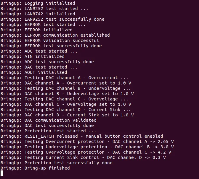
As shown in the example above, the procedure first initializes the logging subsystem and validates the Ethernet PHY. It then performs the EEPROM read/write test, initializes the ADC subsystem, and exercises all four DAC channels individually.
The protection validation follows the DAC test. At this point, the RESET_LATCH line is released for manual button control and the predefined overcurrent, undervoltage, overvoltage, and current-sink reference values are applied sequentially.
For the DAC and protection stages, the UART output should be used together with physical measurements on the corresponding board test points. Since each DAC value is held for several seconds, the generated analog signals can be conveniently verified using a multimeter or oscilloscope.
The RGB LED provides an additional visual indication of the bring-up state. Successful validation stages are indicated in green, while a critical failure switches the LED to red and terminates the bring-up task.
A successfully completed sequence ends with:
BringUp: Protection test successfully done
BringUp: Bring-up finished
Once this message is displayed and the required analog measurements have been verified, the newly assembled board has completed the bring-up sequence.
After the board successfully passes the bring-up procedure, the same source tree can simply be rebuilt with:
#define CONF_BRINGUP_ENABLE 0
to produce the standard OpenEPT application firmware.
Using the production source tree for bring-up keeps PCB validation and the application firmware in sync. New board-level tests can also be added to the bring-up task as the hardware evolves.
Firmware and GUI Upgrade
Firmware Upgrade
The firmware was updated alongside the PCB redesign. Rather than adding board-specific accesses in the application code, the new peripherals were integrated into the existing driver structure so that the rest of the firmware can use them through the same abstractions as before.
The most important firmware additions introduced in this development cycle are:
- Support for the new external DAC6578, including initialization, I2C communication, independent channel control, output enable/disable functionality, software reset, and conversion between physical voltage values and DAC digital codes. The implementation is provided through
dac6578.canddac6578.h, while the device is exposed to the rest of the firmware through the existing analog-output abstraction implemented indrv_aout.canddrv_aout.h. - Support for the on-board EEPROM, providing non-volatile memory access required for persistent device configuration. The M24C32 driver implemented in
m24c32.candm24c32.hprovides initialization, communication verification, single- and multi-byte read/write operations, page-aware writes, and memory-range validation. - Extension of the analog-output abstraction to support multiple independently controlled external DAC channels instead of relying only on the MCU internal DAC.
- Voltage-based analog-output control, allowing higher firmware layers to configure analog references directly in volts rather than operating with raw DAC codes.
- Firmware infrastructure for programmable protection configuration, where DAC-generated reference voltages can be used to configure the redesigned overcurrent, undervoltage, and overvoltage protection circuitry.
- Firmware infrastructure for persistent configuration storage, providing the low-level non-volatile memory functionality required by the parameter-storage mechanism.
The two main low-level additions are the external DAC and EEPROM drivers. Both are kept behind dedicated driver interfaces; application code does not access either device directly.
DAC6578 Support
The redesigned Energy Profiler introduces the Texas Instruments DAC6578, a 10-bit, eight-channel DAC connected to the MCU through an I2C interface. A dedicated hardware abstraction module was therefore added to the firmware in dac6578.c and dac6578.h.
The driver provides the functionality required by the Energy Profiler to initialize the DAC, write values to individual channels, control the state of individual outputs, and perform a software reset of the device. The driver also defines the conversion between physical output voltage and the corresponding 10-bit DAC code.
#define DAC6578_RESOLUTION_BITS          10U
#define DAC6578_FS_VOLTAGE               5.0f
#define DAC6578_MAX_VALUE                1023U

#define DAC6578_FLOAT_TO_DVALUE(v) \
    ( (uint16_t)( \
        ((v) <= 0.0f) ? 0U : \
        ((v) >= DAC6578_FS_VOLTAGE) ? DAC6578_MAX_VALUE : \
        ( ( (v) / DAC6578_FS_VOLTAGE ) * (float)DAC6578_MAX_VALUE + 0.5f ) \
    ) )
The conversion is kept in the driver, so higher layers can work in volts instead of passing raw 10-bit DAC values around the application.
The DAC6578 driver itself is not accessed directly by higher-level OpenEPT services. Instead, it has been integrated into the existing Analog Output driver implemented in drv_aout.c and drv_aout.h. The analog-output interface now exposes the individual external DAC channels through the drv_aout_channel_t abstraction.
typedef enum
{
    DRV_AOUT_CHANNEL_A = 0,
    DRV_AOUT_CHANNEL_B = 1,
    DRV_AOUT_CHANNEL_C = 2,
    DRV_AOUT_CHANNEL_D = 3,
    DRV_AOUT_CHANNEL_E = 4,
    DRV_AOUT_CHANNEL_F = 5,
    DRV_AOUT_CHANNEL_G = 6,
    DRV_AOUT_CHANNEL_H = 7
} drv_aout_channel_t;
For the current Energy Profiler hardware, channels A–D are used by the programmable analog circuitry. The Analog Output driver initializes and resets the external DAC together with the existing analog-output subsystem:
drv_aout_status_t DRV_AOUT_Init()
{
    if(prvDRV_AOUT_Init_Internal() != DRV_AOUT_STATUS_OK)
        return DRV_AOUT_STATUS_ERROR;

    prvDRV_AOUT_DAC_ACTIVE_STATUS = DRV_AOUT_ACTIVE_STATUS_DISABLED;

    if(HAL_DAC_SetValue(&prvDRV_AOUT_DAC_HANDLER,
                        DAC_CHANNEL_2,
                        DAC_ALIGN_12B_R,
                        0) != HAL_OK)
        return DRV_AOUT_STATUS_ERROR;

    HAL_DAC_Stop(&prvDRV_AOUT_DAC_HANDLER, DAC_CHANNEL_2);

    if(DAC6578_Init() != DAC6578_STATUS_OK)
        return DRV_AOUT_STATUS_ERROR;

    if(DAC6578_Reset(1000) != DAC6578_STATUS_OK)
        return DRV_AOUT_STATUS_ERROR;

    return DRV_AOUT_STATUS_OK;
}
Most importantly, higher firmware layers can now request an analog output directly as a voltage:
drv_aout_status_t DRV_AOUT_SetVoltage(float voltage, drv_aout_channel_t channel)
{
    uint16_t dval = DRV_AOUT_ConvertFloatToDigital(voltage);
    return DRV_AOUT_SetValue(dval, channel);
}
This abstraction is particularly important for the new programmable protection circuitry. Instead of calculating and manipulating DAC codes throughout the application, protection thresholds can be represented as physical configuration parameters and converted to the required analog reference at the driver boundary.
EEPROM Support
The second major low-level firmware addition is support for the on-board M24C32 EEPROM, which provides the non-volatile storage required by the new persistent configuration mechanism.
A dedicated EEPROM hardware abstraction module has been introduced in m24c32.c and m24c32.h. The driver provides a compact interface for initialization, communication verification, and read/write access:
m24c32_status_t M24C32_Init(void);
m24c32_status_t M24C32_Ping(uint32_t timeout);

m24c32_status_t M24C32_WriteByte(uint16_t memAddr, uint8_t data, uint32_t timeout);
m24c32_status_t M24C32_ReadByte(uint16_t memAddr, uint8_t* data, uint32_t timeout);

m24c32_status_t M24C32_Write(uint32_t memAddr, const uint8_t* data, uint16_t size, uint32_t timeout);
m24c32_status_t M24C32_Read(uint32_t memAddr, uint8_t* data, uint16_t size, uint32_t timeout);
In addition to basic read and write operations, the implementation handles EEPROM-specific requirements internally. Memory accesses are validated before communication is started, while larger write operations are automatically divided according to EEPROM page boundaries.
while(remaining > 0U)
{
    pageOffset = (uint32_t)(currentAddr % M24C32_PAGE_SIZE_BYTES);
    spaceInPage = (uint32_t)(M24C32_PAGE_SIZE_BYTES - pageOffset);
    chunkSize = (remaining < spaceInPage) ? remaining : spaceInPage;

    if(prvM24C32_WritePage(currentAddr, data, chunkSize, timeout) != M24C32_STATUS_OK)
    {
        return M24C32_STATUS_ERROR;
    }

    currentAddr = (uint32_t)(currentAddr + chunkSize);
    data += chunkSize;
    remaining = (uint32_t)(remaining - chunkSize);
}
Page boundaries, address checks, and the EEPROM write sequence are handled inside the driver. The parameter-storage code therefore only needs a simple non-volatile read/write interface.
The introduction of EEPROM support is particularly important because configuration parameters no longer need to exist only in volatile RAM or as compile-time constants. Parameters can now be stored on the Energy Profiler itself and restored after a power cycle, providing the firmware foundation for persistent device configuration and the corresponding configuration-management functionality exposed through the GUI.
Foundation for Programmable Protection and Persistent Configuration
The DAC and EEPROM additions are closely related to the broader objective of this firmware upgrade. The external DAC provides the actuation mechanism required to generate configurable analog reference levels, while the EEPROM provides the non-volatile storage mechanism required to preserve the associated configuration.
Together, these two additions allow the redesigned Energy Profiler to move from predominantly fixed hardware configuration toward a software-configurable architecture. Protection limits and other device parameters can be represented at higher firmware layers, stored persistently in non-volatile memory, and translated into the corresponding hardware configuration when the device is initialized.
The following sections describe how these low-level capabilities are integrated into the Energy Profiler parameter-management architecture and exposed to the user through the upgraded OpenEPT GUI.
The complete source code for the upgraded OpenEPT Energy Profiler firmware is publicly available in the OpenEPT Git repository. The repository contains the complete firmware project, including the newly introduced DAC6578 and EEPROM drivers, the extended analog-output abstraction, and the firmware infrastructure required for programmable protection and persistent device configuration.
OpenEPT Energy Profiler firmware source code
For users who want to program the Energy Profiler without rebuilding the firmware from source, a prebuilt binary image of the upgraded firmware is also provided. This image can be programmed directly to the Energy Profiler MCU using STM32CubeProgrammer or another compatible STM32 programming tool.
Download the OpenEPT Energy Profiler latest firmware binary
The binary corresponds to the standard OpenEPT application firmware and is intended for normal operation of the redesigned Energy Profiler hardware.
GUI Upgrade
The GUI was updated at the same time as the firmware. Besides adding new functions, we also removed controls that belonged to older versions of the acquisition path and reorganized the remaining settings around the way the profiler is actually used.
While the previous GUI was primarily focused on device connection, acquisition configuration, visualization of voltage and current measurements, and basic load control, the new version introduces a broader device-management architecture. In addition to the existing acquisition functionality, the GUI now provides dedicated interfaces for real-time measurement statistics, device calibration, device configuration, persistent parameter management, and application-level configuration.
A large part of this work was simply removing controls that no longer belong in the main acquisition window. Settings that are obsolete for the current hardware were dropped, while less frequently used device parameters were moved to the configuration dialogs. The main view is now limited to parameters and actions that are normally needed while taking a measurement.
One change that makes a noticeable difference in normal use is the sampling-period setting. The old GUI exposed ADC-oriented parameters such as resolution, sample time, and clock division, so setting the acquisition rate required some knowledge of the ADC configuration. The new GUI replaces these controls with a single Sampling Period [us] field. The requested period is entered directly in microseconds and the low-level setup is handled by the firmware.
For an energy-profiling experiment, the sampling period is the quantity the user actually needs to choose; the ADC timing details are an implementation detail. Moving that calculation out of the GUI makes acquisition setup shorter and less error-prone.
The removal of redundant controls is equally important for the overall usability of the application. The redesigned interface deliberately avoids exposing commands and configuration fields simply because they exist at a lower firmware or hardware level. Instead, controls are presented according to their role in the Energy Profiler workflow. Frequently used acquisition parameters remain in the main window, advanced device parameters are handled through the Device Configuration interface, and application-specific settings are moved to the Application Configuration dialog. This results in a cleaner interface with fewer opportunities for inconsistent or unnecessary configuration.
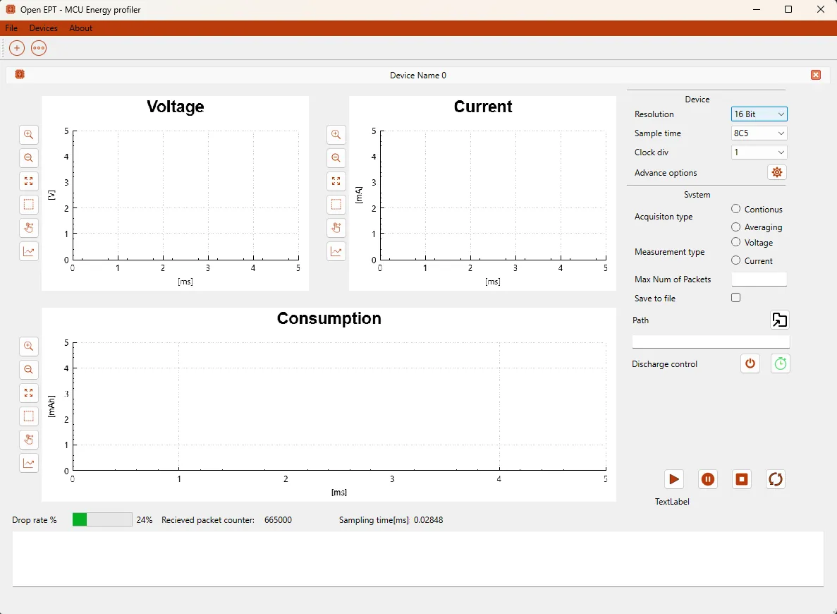
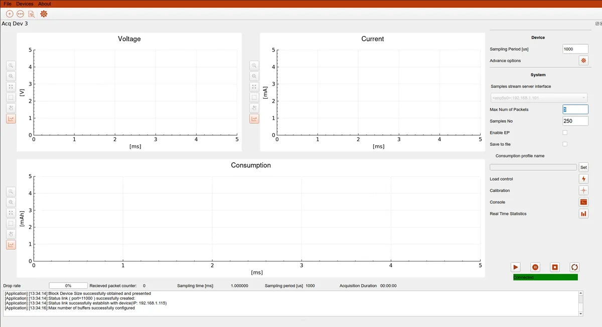
The main GUI additions introduced in this development cycle are:
- Real-Time Statistics, providing continuously updated statistical information calculated from the acquired measurement data;
- Calibration interface, introducing the graphical infrastructure required for configuring and executing Energy Profiler calibration procedures;
- Device Configuration interface, providing structured access to device, network, acquisition, Energy Point, and other firmware parameters;
- Persistent configuration controls, introducing dedicated operations for acquiring, modifying, applying, storing, and resetting device parameters;
- Application Configuration, separating application-level settings such as the workspace and communication-service configuration from individual Energy Profiler device parameters;
- Improved device control panel, reorganizing acquisition, load control, calibration, console, and statistics functionality into dedicated actions while keeping the main acquisition view focused on measurement visualization.
These changes provide the GUI foundation required for the new firmware and hardware architecture and, more importantly, establish a clearer separation between measurement acquisition, device configuration, device calibration, and application configuration.
The latest version of OpenEPT GUI is available for Linux in two formats. The Debian package can be used for standard installation on Debian/Ubuntu-based systems, while the AppImage provides a standalone version that can be executed without installation.
The complete OpenEPT GUI source code is publicly available on GitHub.
Download Linux standalone AppImage
Important: When using OpenEPT on Linux, make sure that the application network ports are allowed by the system firewall. The default ports are 6100 (Stream Service), 11000 (Status Service), and 8000 (Energy Point Service). If the port configuration is changed in the application, the firewall configuration must be updated accordingly.
Main Acquisition Interface
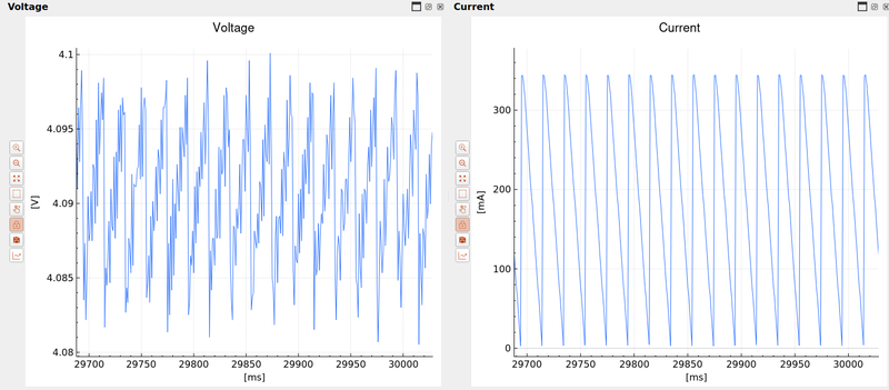
The main acquisition interface has been reorganized while preserving the familiar voltage, current, and accumulated consumption plots.
The right-hand control panel has been simplified and now concentrates on the parameters and actions required during an acquisition session. The sampling period, communication interface, maximum number of packets, number of samples, Energy Point functionality, file storage, and consumption-profile settings are available directly from the main view.
Dedicated actions are provided for:
- Load Control
- Calibration
- Console
- Real-Time Statistics
This organization keeps the frequently used acquisition controls immediately accessible while moving more complex device configuration to dedicated configuration dialogs.
The bottom status area has also been extended to provide acquisition-related information such as the packet drop rate, received packet count, sampling time, sampling period, and acquisition duration. Together with the application log, this provides considerably more information about the state of an active measurement session than the previous GUI version.
Real-Time Statistics
A new Real-Time Statistics module has been introduced to provide an immediate numerical summary of the acquired data without requiring the user to stop the acquisition or export the measurement for offline processing.
The statistics window is accessible directly from the main device interface and operates on the measurement samples received during the active acquisition session.
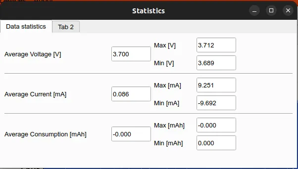
For the main measured quantities, the interface currently provides:
- Average value
- Maximum value
- Minimum value
These statistics are calculated independently for:
- Voltage [V]
- Current [mA]
- Accumulated consumption [mAh]
The values are updated from the acquired measurement stream and provide a compact numerical representation complementary to the real-time plots.
For example, while the voltage and current graphs remain useful for observing transient behavior and changes over time, the statistics interface allows the user to immediately determine the observed voltage range, current extrema, and average operating conditions.
This is particularly useful during energy profiling experiments where both the temporal behavior and aggregate characteristics of the measured workload are relevant. It also allows basic measurement verification to be performed directly during acquisition without requiring a separate post-processing step.
The Real-Time Statistics module has been implemented as a separate interface so that additional statistics and derived quantities can be introduced in future versions without increasing the complexity of the main acquisition window.
Device Configuration Interface
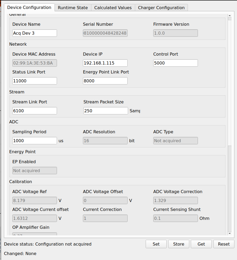
A major architectural GUI change is the introduction of a dedicated Device Configuration interface.
Previously, a significant part of the device configuration was either exposed directly through the acquisition window or handled internally by the application. The new interface provides a structured representation of the parameters maintained by the Energy Profiler firmware.
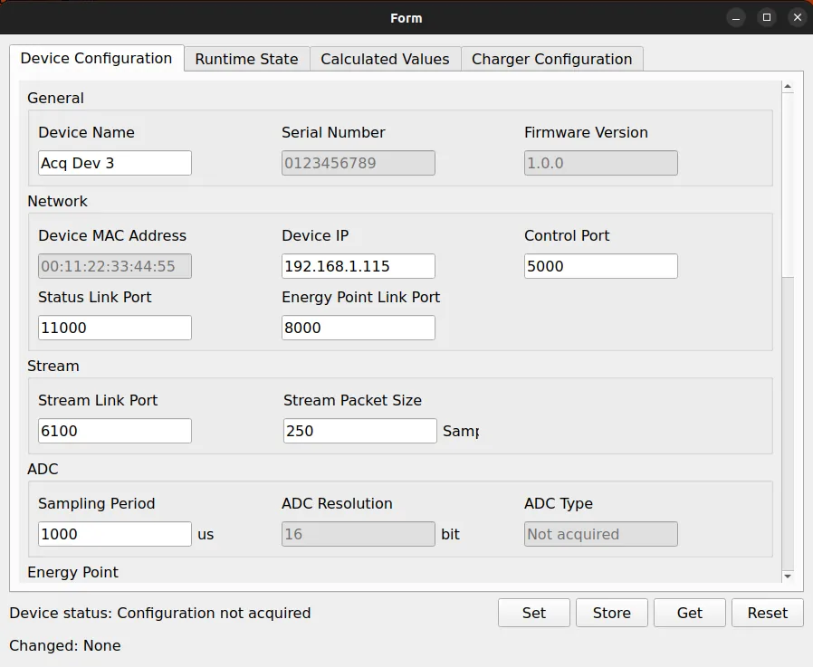
The configuration interface is divided into several logical groups. The current implementation exposes parameters related to:
- general device information;
- network configuration;
- communication service ports;
- measurement stream configuration;
- ADC and sampling configuration;
- Energy Point functionality;
- additional device-specific parameters.
The interface distinguishes between parameters that can be modified by the user and parameters that are acquired from the device and presented as read-only information. For example, firmware version, serial number, hardware-dependent information, and other device properties can be presented alongside configurable parameters without allowing accidental modification.
The configuration dialog also introduces a common set of parameter-management operations:
- Get – acquire the current parameter values from the connected Energy Profiler;
- Set – apply modified parameter values to the device;
- Store – request persistent storage of the current configuration;
- Reset – restore or reset the corresponding device configuration.
The GUI additionally tracks whether configuration parameters have been acquired and whether values have been changed locally. This provides the basis for a more controlled configuration workflow and reduces the possibility of unintentionally overwriting device parameters.
The graphical infrastructure and a substantial part of the Device Configuration interface have been implemented as part of the current GUI upgrade. However, this functionality is directly related to the new firmware parameter-storage architecture and EEPROM-based persistent storage. The complete integration, final parameter organization, and detailed description of the persistent configuration workflow will therefore be further developed and documented within the dedicated file/parameter system milestone.
Application Configuration
Device-specific parameters are now separated from settings belonging to the OpenEPT desktop application itself.
A dedicated Application Configuration dialog has been introduced for this purpose.
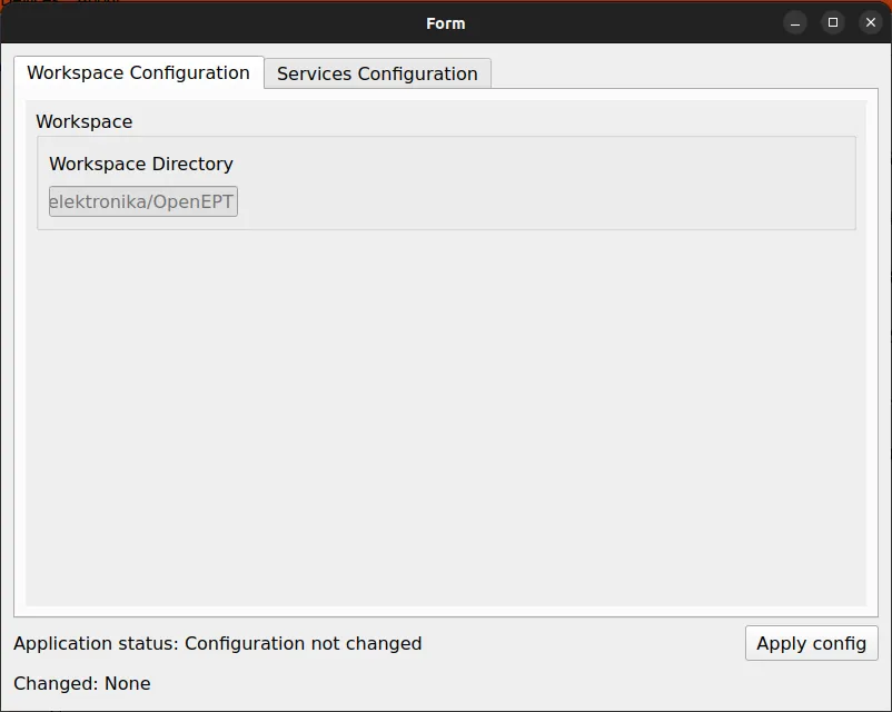
The Workspace Configuration section defines the directory used by the OpenEPT application for storing and managing application data and generated measurement files.
Communication services are configured independently through the Services Configuration tab:
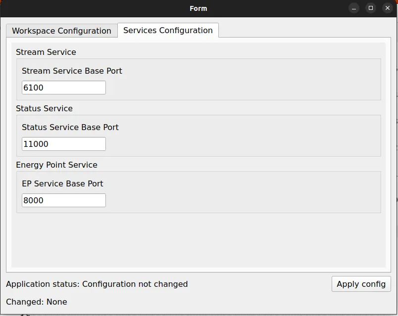
The interface currently provides configuration of the base ports used by the main OpenEPT communication services, including:
- Stream Service
- Status Service
- Energy Point Service
Separating these settings from the Energy Profiler device configuration creates a clearer distinction between parameters that describe the physical device and parameters that control the behavior of the host application.
This separation is particularly important when multiple Energy Profiler devices are used with the same OpenEPT application instance, since application-level communication and workspace settings should not be treated as properties of an individual measurement device.
Calibration Interface
A dedicated Calibration interface has also been introduced as part of the GUI upgrade.
The purpose of this interface is to provide a centralized graphical environment for calibration-related operations rather than exposing calibration functionality through individual low-level controls.
The new GUI infrastructure establishes the foundation required for interaction with calibration parameters and procedures implemented by the Energy Profiler firmware. This is particularly important for the redesigned hardware, where accurate mapping between measured electrical quantities, ADC values, analog control signals, and physical units must be maintained in a structured manner.
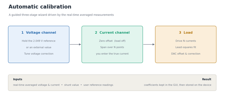
A significant part of the graphical interface required for calibration has been developed during the current milestone. However, the calibration workflow is intentionally not considered complete within this GUI upgrade.
The calibration functionality will be further developed, integrated with the corresponding firmware parameter mechanisms, and described in detail within the dedicated calibration milestone. That milestone will cover the complete calibration procedure, storage and retrieval of calibration parameters, and their interaction with the Energy Profiler measurement chain.
The current implementation should therefore be considered the graphical and architectural foundation for the complete calibration subsystem rather than its final functional version.
GUI Support for the New Firmware Architecture
The GUI changes introduced in this milestone are closely coupled with the firmware extensions described in the previous section.
The firmware now provides the low-level mechanisms required for programmable analog control and non-volatile parameter storage, while the GUI provides the user-facing infrastructure required to configure and inspect these capabilities.
The resulting architecture separates the system into several distinct layers:
- Hardware and low-level drivers provide access to the ADC, DAC, EEPROM, protection circuitry, and other Energy Profiler peripherals.
- Firmware parameter and configuration services provide a structured representation of device configuration and persistent parameters.
- GUI configuration interfaces expose these parameters to the user through dedicated device, calibration, and application configuration views.
- Acquisition and analysis interfaces remain focused on measurement control, visualization, real-time statistics, and energy profiling.
This separation is an important step toward making the Energy Profiler easier to configure and maintain as the number of supported hardware and firmware parameters increases.
At the same time, the GUI upgrade has been designed so that the interfaces introduced during this milestone can be incrementally extended. In particular, the Calibration and Device Configuration interfaces will continue to evolve as part of the dedicated calibration and file/parameter-system milestones, where their complete firmware integration and workflows will be finalized and documented.
Hardware Redesign
The PCB was revised in several areas, although the main functional blocks remain the same: measurement, protection, load control, Ethernet communication, and MCU processing. Most of the redesign work focused on making previously fixed analog settings programmable and adding the hardware needed for persistent configuration and charger integration.
The most important hardware changes include:
- introduction of a new multi-channel external DAC for programmable analog control;
- programmable overcurrent, undervoltage, and overvoltage protection thresholds;
- programmable control of the current sink;
- integration of an on-board EEPROM for persistent device configuration;
- addition of a dedicated interface for the external charger board;
- redesign of several protection and power-path circuits;
- improved battery-presence and load-control circuitry;
- redesigned connectors and additional hardware test/diagnostic points;
- improved visual indication of system states and relevant hardware events;
- updated voltage-reference circuitry supporting the analog subsystem.
The complete electrical schematic of the redesigned OpenEPT Energy Profiler is publicly available as part of the OpenEPT Git repository and can be accessed here. It provides the complete circuit-level description of the board, including the measurement chain, programmable protection circuitry, current sink, power supplies, communication interfaces, EEPROM, and charger-board interface. The schematic can therefore be used as the primary hardware reference for all functional blocks discussed below.
The front side of the redesigned OpenEPT Energy Profiler PCB is shown below, with the main functional blocks, connectors, controls, and test points accessible directly on the board.
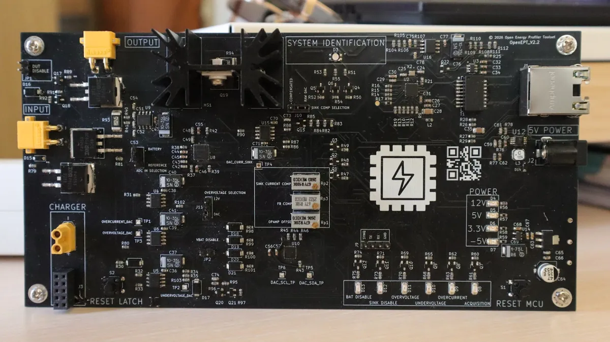
To make the new board easier to use during measurement, calibration, and hardware testing, the main user-accessible connections, status indicators, and hardware-selection jumpers are summarized below.
Board Connections
The redesigned Energy Profiler provides dedicated connections for the battery, Device Under Test (DUT), charger board, host communication, and system power.
| PCB Label | Interface | Description |
|---|---|---|
| CHARGER | Charger connection | Connection to the external charger board, providing both the charger power connection and the communication/control interface required for charger integration. |
| INPUT | Battery input | XT30 connector used to connect the battery to the Energy Profiler. |
| OUTPUT | DUT output | XT30 connector used to connect the Device Under Test (DUT) whose energy consumption is being measured. |
| 5V POWER | System power supply | Barrel connector used to provide the 5 V supply for the Energy Profiler electronics. |
| RJ45 | Ethernet | Ethernet interface used for communication between the Energy Profiler and the OpenEPT host application. |
| J9 | DUT profiling interface | Dedicated interface used for profiling the energy consumption of the Device Under Test. |
Hardware Status Indicators
A set of dedicated LEDs provides immediate information about the state of the power path, current sink, acquisition subsystem, and hardware protection circuits.
| PCB Label | Indication | Description |
|---|---|---|
| BAT DISABLE | Battery disabled | Indicates that the battery is disconnected from the corresponding power path. |
| SINK DISABLE | Current sink disabled | Indicates that the programmable current sink is not active. |
| ACQUISITION | Acquisition active | Blinks while measurement acquisition is in progress. |
| OVERVOLTAGE | Overvoltage protection | Indicates that the overvoltage protection has been triggered. |
| UNDERVOLTAGE | Undervoltage protection | Indicates that the undervoltage protection has been triggered. |
| OVERCURRENT | Overcurrent protection | Indicates that the overcurrent protection has been triggered. |
| SYSTEM IDENTIFICATION | System status | RGB LED used to indicate the current operating state of the Energy Profiler. |
These indicators are particularly useful during hardware bring-up and debugging because the state of the main protection and control signals can be observed directly on the PCB without relying only on the GUI or UART log.
Hardware Selection Jumpers
Three on-board jumpers provide direct hardware selection of several analog signal paths. They are primarily intended for normal operation, calibration, and hardware testing.
| PCB Label | Selection | Options | Description |
|---|---|---|---|
| J11 | Overvoltage Selection | DAC (default) / 12 V | Selects the reference used by the overvoltage protection circuit. The default DAC position allows the overvoltage threshold to be configured programmatically, while the alternative position uses the fixed 12 V reference. |
| J12 | Voltage Input Selection | Battery (default) / Voltage Reference | Selects the signal connected to the voltage measurement path. Battery voltage is used during normal operation, while the voltage-reference input is provided for calibration. |
| J10 | Current Sink Voltage Selection | RAW DAC (default) / COMPENSATED | Selects between the direct DAC output and the offset-compensated current-sink control signal. Since a zero DAC code does not result in exactly 0 A sink current, the compensated path can be selected when analog offset compensation is required. |
The default jumper configuration is intended for normal Energy Profiler operation. The alternative positions provide direct access to the reference and compensated signal paths required during calibration, characterization, and low-level hardware testing.
Programmable Analog Control
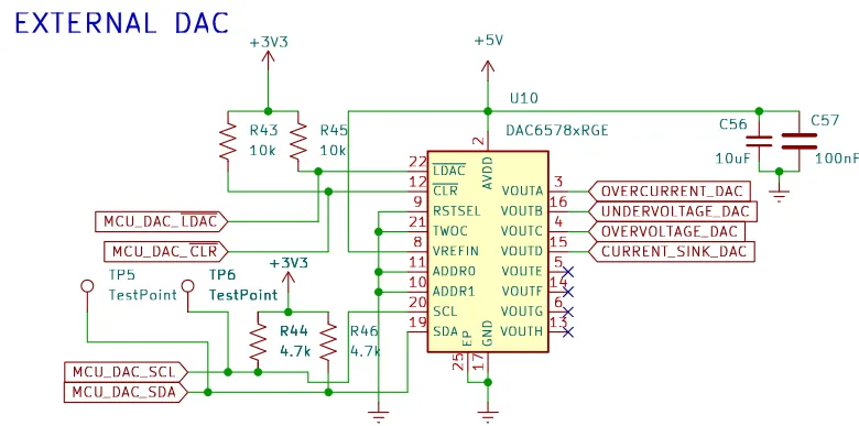
One of the most important changes in the redesigned Energy Profiler is the introduction of a dedicated multi-channel external DAC. The new design uses the DAC6578, controlled directly by the MCU through an I2C interface.
Four DAC outputs are currently used by the Energy Profiler:
- Channel A – Overcurrent protection
- Channel B – Undervoltage protection
- Channel C – Overvoltage protection
- Channel D – Current Sink control
In the previous revision, several of these analog settings depended on fixed component values, potentiometers, or simpler GPIO-controlled circuitry. They are now generated by the DAC and can be changed from firmware.
As a result, the firmware can configure the analog operating limits according to the currently stored device configuration. This also establishes a direct connection between the hardware redesign, the new firmware parameter system, and the configuration interface introduced in the OpenEPT GUI.
Programmable Protection Thresholds
The overcurrent, undervoltage, and overvoltage protection circuits were redesigned to operate with the programmable reference voltages generated by the external DAC.
Instead of treating the protection thresholds as fixed hardware properties of the board, the new architecture makes them configurable device parameters. The firmware can therefore modify the protection limits without requiring hardware changes or manual adjustment of on-board potentiometers.
The three principal protection reference signals are:
OVERCURRENT_DACUNDERVOLTAGE_DACOVERVOLTAGE_DAC
These signals are connected to the corresponding analog protection circuits, while the resulting protection states remain available to both the latch circuitry and the MCU.
This approach makes the Energy Profiler considerably more flexible when operating with different batteries, supply voltages, current ranges, or devices under test. At the same time, the hardware protection remains implemented independently of the normal software execution path, preserving the ability to react directly to unsafe electrical conditions.
Programmable Current Sink
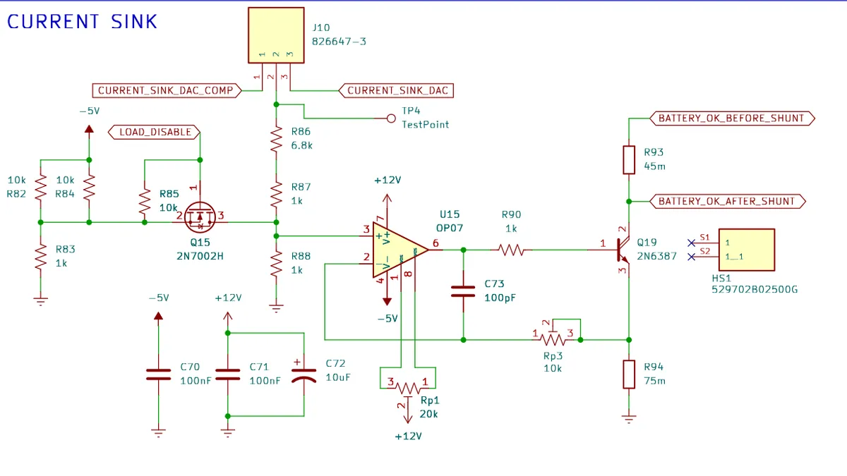
The current-sink circuit was also integrated into the new programmable analog-control architecture. A dedicated DAC channel, CURRENT_SINK_DAC, is used to define the current-sink operating point.
The redesigned circuit includes the analog control path, power transistor stage, current-sense resistor, and additional DAC offset-compensation circuitry. The latter provides a hardware mechanism for compensating the analog offset of the current-sink control path.
This allows the current sink to be controlled from firmware through the same analog-output subsystem used for programmable protection thresholds and provides a foundation for more repeatable battery discharge and characterization experiments.
On-Board EEPROM
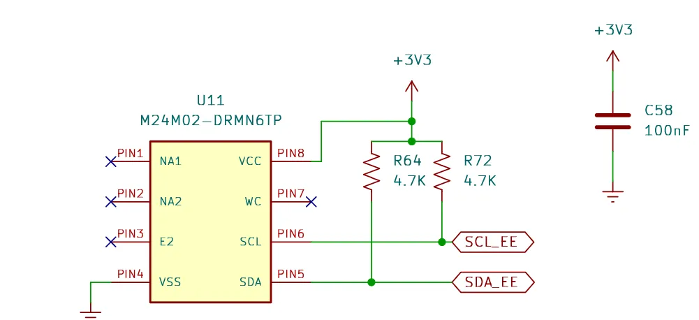
A dedicated non-volatile memory device has been added directly to the Energy Profiler PCB. The new board integrates an M24M02 EEPROM, connected to the MCU through the SDA_EE and SCL_EE I2C signals.
The EEPROM provides persistent storage for device-specific configuration parameters. This is particularly important after introducing programmable hardware parameters, since protection thresholds, calibration parameters, device configuration, and other settings can now remain associated with a particular Energy Profiler board across power cycles.
The EEPROM therefore provides the hardware foundation for the persistent parameter-storage mechanism described in the firmware and GUI sections above.
Charger Board Interface
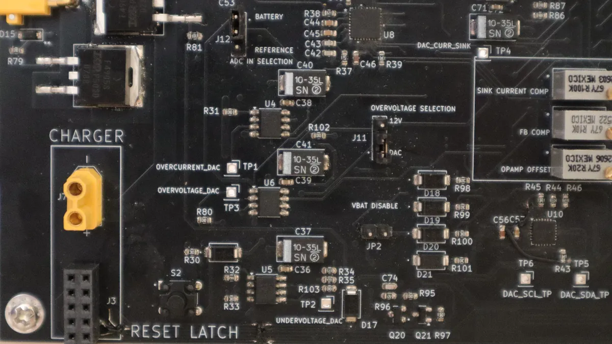
Another major addition is a dedicated hardware interface for connecting an external charger board.
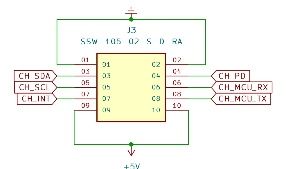
The redesigned board exposes the required charger communication and control signals, including:
CH_SDACH_SCLCH_INTCH_PDCH_MCU_TXCH_MCU_RX
Together, these signals provide both digital communication and charger-control capabilities and allow the Energy Profiler and charger hardware to operate as parts of the same experimental platform.
This interface is particularly important for the next stages of OpenEPT development, where energy profiling, battery characterization, controlled discharge, and battery charging can be combined within the same hardware and software environment.
The physical implementation of the charger interface is shown below, including the dedicated charger connector and the related interface components on the Energy Profiler PCB.
Redesigned Protection and Power Path
The protection subsystem was redesigned to provide programmable protection thresholds while preserving a hardware-based protection path that operates independently of the firmware.
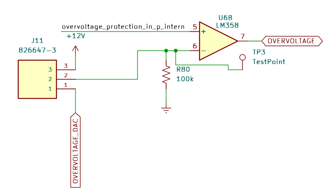
Three main protection mechanisms are implemented: overvoltage, undervoltage, and overcurrent protection. Their thresholds are defined by dedicated outputs of the external DAC (OVERVOLTAGE_DAC, UNDERVOLTAGE_DAC, and OVERCURRENT_DAC), allowing the protection limits to be configured directly from the Energy Profiler firmware.
The overvoltage protection circuit compares the monitored battery voltage against the programmable OVERVOLTAGE_DAC reference. When the configured threshold is exceeded, the circuit generates the OVERVOLTAGE signal, which is subsequently propagated to the protection latch circuitry.
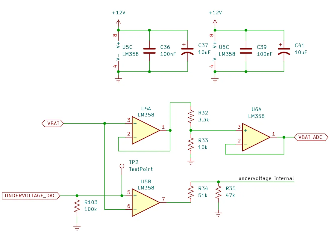
The undervoltage circuit performs a similar function for the lower battery-voltage limit. The battery voltage is buffered and conditioned both for voltage measurement (VBAT_ADC) and protection purposes. The UNDERVOLTAGE_DAC signal defines the programmable undervoltage threshold, while the comparator output generates the internal undervoltage fault signal.
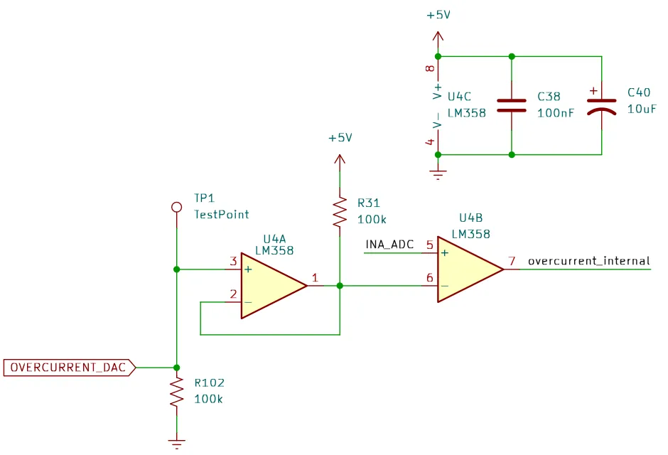
Overcurrent protection is based on the measured current signal INA_ADC, obtained from the current-sense amplifier. This signal is compared against the reference generated by the OVERCURRENT_DAC channel. When the measured current exceeds the configured limit, the comparator generates the overcurrent_internal protection signal.
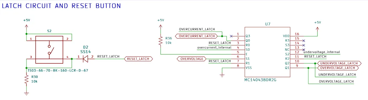
The outputs of the three protection circuits are connected to a dedicated hardware latch implemented using the MC14043B. Once an overcurrent, undervoltage, or overvoltage condition is detected, the corresponding state is stored by the latch and remains active even if the original fault condition disappears. This prevents short transient recovery from automatically re-enabling the protected path.
The latched protection state can be cleared using the RESET_LATCH signal. A dedicated push button is provided for manual reset, while the same reset mechanism can also be controlled by the system when required.
In addition to controlling the protection circuitry, the latched protection signals are routed to the MCU through dedicated signal-conditioning circuitry. This allows the firmware to independently determine whether an overcurrent, undervoltage, or overvoltage event has occurred. The same signals are also connected to dedicated indicator circuits, which activate the corresponding LEDs and therefore provide an immediate visual indication of the detected protection condition.
This creates two complementary diagnostic paths: the MCU can detect and report the protection state through the software interface, while the LEDs provide direct hardware-level indication even during board bring-up or firmware debugging.
In short, the firmware sets the protection thresholds through the DAC, but detection and latching remain hardware functions. The MCU reads the latched states, and dedicated LEDs show the same protection events on the board.
Improved Hardware Status Indication
The redesigned board provides more extensive visual indication of both system operation and specific hardware events.
In addition to the RGB system-status indication, dedicated indication circuits are provided for relevant protection and control signals. This makes it possible to observe important hardware states directly during development, PCB bring-up, and debugging without relying exclusively on firmware logging.
This feature is particularly useful together with the dedicated bring-up firmware described earlier, since UART diagnostics, RGB system status, dedicated event LEDs, and electrical measurements at the available test points can be used together when validating a newly assembled board.
Updated Voltage References
The analog-support circuitry was also reorganized around dedicated voltage-reference and supply-generation blocks. The redesigned board provides the voltage rails and references required by the measurement, DAC, protection, and current-sink circuits, including dedicated +12 V, +3.3 V, -5 V, and precision 2.048 V reference circuitry.
The precision reference is particularly important for maintaining a well-defined analog reference within the measurement and programmable-control signal chain.
Hardware Designed for Configuration Rather Than Fixed Operation
The previous board already covered measurement, protection, and load control, but a number of operating limits were still tied directly to the component configuration on the PCB.
In the redesigned version, substantially more of the analog behavior is exposed as programmable device configuration. Protection thresholds and current-sink control are generated through the external DAC, configuration parameters can be retained in the on-board EEPROM, and dedicated interfaces are provided for additional hardware such as the charger board.
This ties the PCB, firmware parameter system, persistent storage, and GUI configuration together instead of treating them as separate additions.